
Tools needed
- small Philips head screwdriver
- pliers or diagonal cutters
- razor knife
- scissors
- solder iron (and solder)
- hot glue gun or Silicon Glue
Parts needed

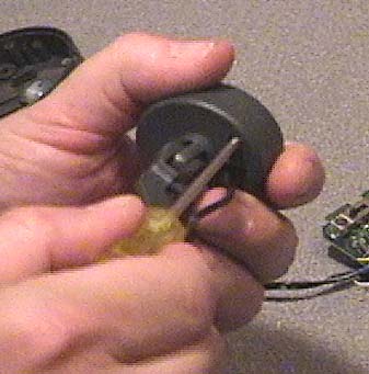
Cut the power cable to the camera then remove the 3 screws from the transmitter base.
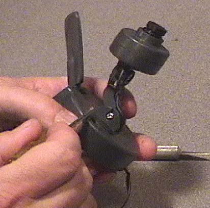
Remove camera pivot screw and nut.
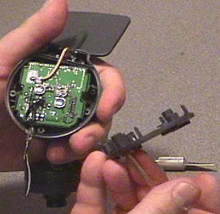
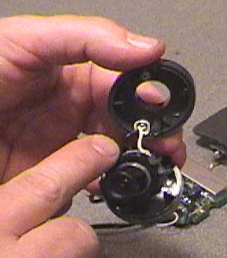
Remove base plate exposing the transmitter.
Pull out the transmitter and antenna, then cut the wires to the transmitter as close as you can to the silicon glue.
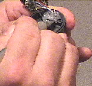
Now, pull the camera wires through the transmitter top, freeing the camera from the transmitter base.
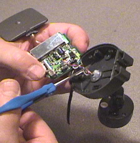
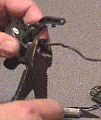
Remove 2 screws from Camera back and open the camera housing.
When you remove the camera front cover plate, be careful when removing the microphone. It's just a press fit, so gently pull it from the socket.
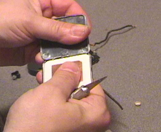
On the camera housing back, use the razor knife to carefully remove the silicon glue from around the wires.
Using diagonal cutters (or pliers) pry out the wire plug and then pull camera wires through the camera back housing.
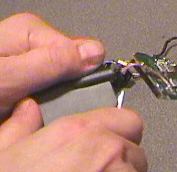
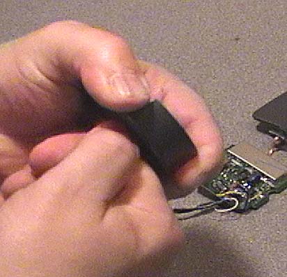
Using a razor knife, carefully split open the antenna cover then...
...peel it away.

You should now have the transmitter and antenna "exposed".
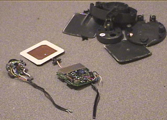
This is what you should have left. On the left, the beginnings of an Vidroc and on the right, a pile of plastic.
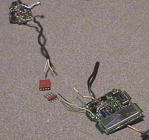
Now it's time to solder on the 4 pin plug connectors.
I put the male plug on the transmitter, but you can do it any way you like.
Note: that though there are 5 wires but you only need a 4 pin plug as the Blue and Black wires both supply negative voltage to the camera.
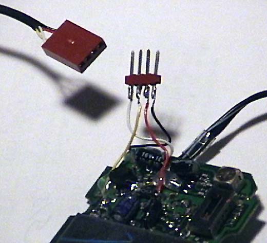
Here are the transmitter and camera with connectors soldered on. For what it's worth I solder the wires (from left to right) White, Yellow, Red then Black.
It's also important to note that these plugs are not keyed so you must pay attention when connecting the plugs as they'll fit either way.
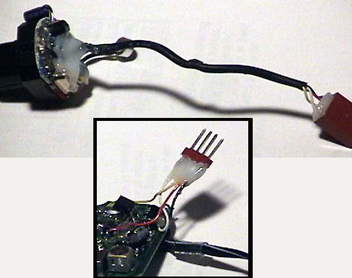
Next add hot glue (or Silicon glue) to secure the wires onto the plugs and camera. This will reduce the chances of a wire getting pulled off or broken. I use hot glue (with the glue gun set to low temp) as it's ready sooner.
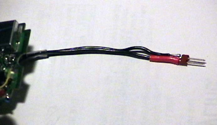
Now solder on the 2 pin male connector to the power leads from the transmitter. I used red heat shrink tubing to mark the positive side of the plug, plus it keeps the plug's soldered pins isolated from each other.
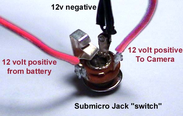
This may be the "trickiest" part of the project, soldering the sub micro switch (mind you it won't be a big deal if you've done this before.)
Solder both 12 volt negative wires to the center contact of the jack.
Solder the 12 volt wire from the battery to the NC (normally closed) side of the jack and the 12 volt wire to the transmitter to the "tip" side of the jack.
That's all there is to that (for now.)
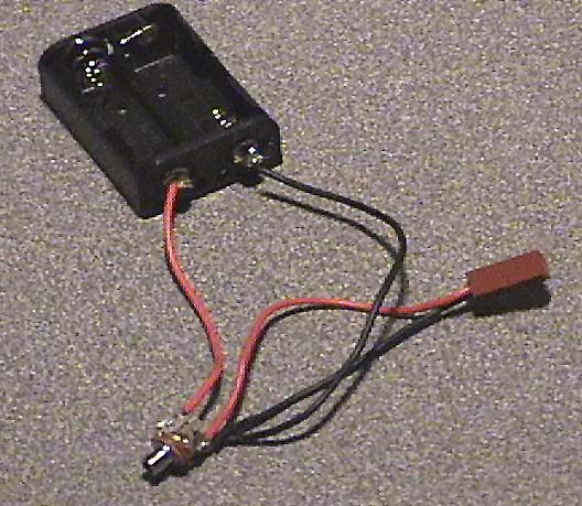
This picture shows the battery holder with micro jack "switch" and plug connector for powering the transmitter.

Take the wire you cut from the camera at the start and solder on the other Submini plug, with the tip being the positive source.
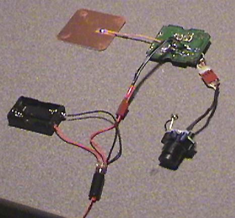
Complete system ready for installing in the rocket.
If you plug in the Submini plug into the jack, (and plug the transformer into a wall socket) you should get a video signal going to the transmitter.